
Contents
- AverLAB Front Panel
- Power LED
- Balanced Analog Generator Outputs A and B
- Unbalanced Analog Generator Outputs A and B
- Analog Generator Active LEDs
- Balanced Analog Analyzer Inputs A and B
- Unbalanced Analog Analyzer Inputs A and B
- Analog Analyzer Input Active LEDs
- Digital Audio Connections
- Lock LED
- S/PDIF In and Out
- Optical In and Out
- AES/EBU In and Out
- Digital Generator Active LED
AverLAB Front Panel
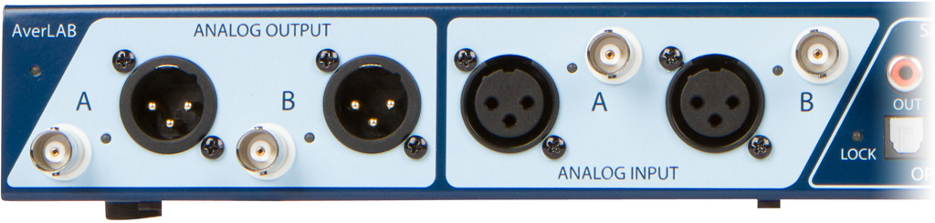
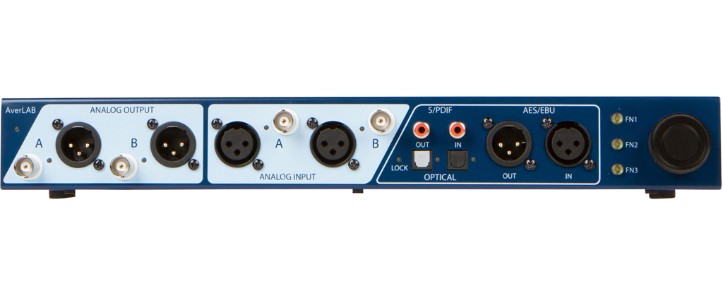
The AverLAB front panel has most of the analog and digital audio connections you will use, along with the knob and buttons that allow control of the software directly from the hardware. From left to right, the connections, LEDs, and controls are:
Power LED
The power LED is in the upper left-hand corner, just under the AverLAB name. In normal operation this will glow white to indicate that the unit is running and that it has passed its self tests. The LED flashes during programming, and during some other operations to indicate the state of the system.
Balanced Analog Generator Outputs A and B
These two XLR connectors are the balanced outputs for the two analog generator channels. They use the industry standard XLR pinout where pin 1 is ground, pin 2 is hot (+), and pin 3 is cold (-).
These are transformerless balanced outputs. Avoid connecting pin 2 or pin 3 directly to ground. AverLAB’s output circuits can tolerate a short to ground for any length of time, but while shorted generator performance may be degraded. In particular, depending on the signal level distortion may be significantly higher in that configuration. In that case, either lift ground to avoid the shorted condition, or use the unbalanced BNC output instead.
To use these outputs, select the Balanced A and/or Balanced B analog outputs for a given test. The outputs are always active, even when not selected. That is, if the unbalanced output is selected for a channel and the generator is on, the balanced connector will also output the same frequency signal. However, it will be 6 dB higher than the signal available from the unbalanced output.
Selecting the balanced output in the test dialog will ensure that the level set for the test is the level output from the unbalanced connector for that channel. In that case, the unbalanced output for that channel will also be active, but its level will be 6 dB lower than the value set in the test. The maximum level that can be set for the balanced outputs is +26 dBu (approximately 15.5 Vrms.)
Unbalanced Analog Generator Outputs A and B
These two BNC connectors are the unbalanced outputs for the two analog generator channels. The center pin is hot (+) and the shell is ground. This ground is electrically connected to the system ground, so care must be taken to prevent ground loops or signal shorts when connecting to a device under test.
To use these outputs, select the Unbalanced A and/or Unbalanced B analog outputs for a given test. The outputs are always active, even when not selected. That is, if the balanced output is selected for a channel and the generator is on, the unbalanced connector will also output the same frequency signal. However, it will be 6 dB lower than the signal available from the balanced output.
Selecting the unbalanced output in the test dialog will ensure that the level set for the test is the level output from the unbalanced connector for that channel. In that case, the balanced output for that channel will also be active, but its level will be 6 dB higher than the value set in the test. The maximum level that can be set for the unbalanced outputs is +20 dBu (approximately 7.75 Vrms.)
Analog Generator Active LEDs
These two green LEDs, located between the BNC and XLR connectors for channels A and B, are lit whenever that generator channel is active. This give an indication at a glance of the state of the generator outputs.
Balanced Analog Analyzer Inputs A and B
These transformerless inputs accept analog input signals for analysis via two XLR connectors. They use the industry standard XLR pinout where pin 1 is ground, pin 2 is hot (+), and pin 3 is cold (-). They accept AC signal levels from zero to +26 dBu (approximately 15.5 Vrms), and DC levels from zero to ±70V. Signals outside of that range may cause AverLAB to disconnect the input connectors from the internal electronics to protect from damage.
To use these inputs, select the Balanced A and/or Balanced B analog inputs for a given test. If the balanced input is selected for a channel the corresponding unbalanced BNC connector is internally disconnected.
Unbalanced Analog Analyzer Inputs A and B
These inputs accept analog input signals for analysis via two BNC connectors. The center pin is hot (+) and the shell is ground. This ground is electrically connected to the system ground, so care must be taken to prevent ground loops or signal shorts when connecting to a device under test. They accept AC signal levels from zero to +20 dBu (approximately 7.75 Vrms), and DC levels from zero to ±35V. Signals outside of that range may cause AverLAB to disconnect the input connectors from the internal electronics to protect from damage.
To use these inputs, select the Unbalanced A and/or Unbalanced B analog inputs for a given test. If the unbalanced input is selected for a channel the corresponding balanced XLR connector is internally disconnected.
Analog Analyzer Input Active LEDs
These two green LEDs, located between the BNC and XLR connectors for each channel, provide a quick indication of input signal presence. They turn on with signals above approximately -60 dBu. Signals below this threshold are still processed normally, but may not light the LED.
Digital Audio Connections
The various front-panel digital audio connections are outlined below. These connectors handle coaxial S/PDIF, Optical S/PDIF (Toslink), ADAT, and AES/EBU signals at sample rates from 44.1 kHz to 192 kHz. Each of the various inputs may be selected as the sync source for clock recovery, as well as external Word Clock (on the rear panel) and the internal crystal oscillator. One set of inputs and outputs may be selected at a time, and analog to digital and digital to analog cross-domain measurements may be made. Currently, it is not possible to select inputs and outputs of different digital formats; both the generator and analyzer use the same format for a given test.
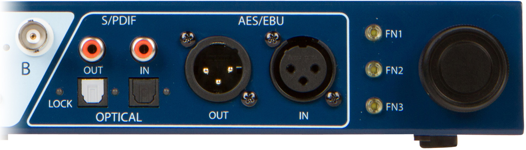
Lock LED
This bi-color (red/green) LED indicates the state of the digital PLL used as the clock regenerator for digital audio inputs and outputs. The LED has three states:
Green indicates that the PLL is locked and regenerating sync from one of the inputs (AES/EBU, Optical, ADAT, or S/PDIF) or from the external Word Clock input on the rear panel.
Red indicates that AverLAB is set to use sync from one of the inputs or from the Word Clock input, but there is no valid signal to provide sync.
Off indicates that AverLAB is set to Internal Sync, and is using it’s internal crystal oscillator as the timebase for sync. Internal sync is always valid, so the LED is off to indicate this condition.
S/PDIF In and Out
These two RCA jacks provide transformer-coupled unbalanced coaxial S/PDIF digital audio input and output for use with consumer digital audio devices. When selected, the output jack is connected to a digital generator, while the input jack drives AverLAB’s digital analyzer.
Optical In and Out
These TOSLINK optical connectors are used for optical S/PDIF and ADAT format digital audio inputs and outputs.
AES/EBU In and Out
These two XLR connectors provide transformer-coupled balanced AES/EBU digital audio input and output for use with professional digital audio devices. When selected, the male output connector is connected to a digital generator, while the female input drives AverLAB’s digital analyzer.
Digital Generator Active LED
Located between the Optical output and input connectors, closer to the output, the green digital generator active LED lights whenever the digital generator is active. This LED functions regardless of the selected format. For example, if AES/EBU is selected, this LED lights when that generator is set to any level greater than -128 dBFS.
Digital Analyzer Input Active LED
This green LED, located to the right of the optical input connector, provides a quick indication of input signal presence. It turns on with any input signal greater than -128 dBFS.
FN1/FN2/FN3 Buttons
These three LED-lit assignable buttons provide direct control of the AverLAB software, as well as system status and user feedback. More information about the states and functions of these buttons is found in the AverLAB Software User’s Manual.
Encoder Knob
This assignable rotary encoder, with machined aluminum knob, provides control of parameters and values in the AverLAB software. The knob has 30 detents per rotation, with excellent feedback of position and fine control of adjustments.
AverLAB Rear Panel
The unit’s rear panel provides connections for power, expansion, control, and Ethernet. These functions are outlined below.
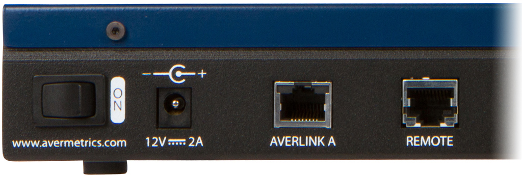
Power Switch
Turns AverLAB on or off, as required. Note that the switch affects DC power; AC wall power is still applied to the external AC/DC adapter even when this switch is turned off.
Power Input
AverLAB requires clean 12V DC, 2A maximum for proper operation. The input connector accepts a standard 5.5mm x 2.1mm, center positive barrel connector. The unit is reverse protected up to 2A, and will survive indefinitely in this state, although it will not function with reverse power applied. The supplied power adapter is carefully selected to ensure AverLAB will meet all its operational specifications. Operation is not guaranteed when using power adapters not supplied by Avermetrics.
AverLink A Port
By using the AverLink™ port, AverLAB’s capabilities can be expanded using existing and future AverLine racks and modules. These modules include 2-channel analog generators and analyzers, multichannel digital modules with up to 16 channels of digital audio each, process control modules, and more. Up to 123 modules may be attached via the AverLink port, and when attached the AverLAB software and hardware act as if those modules were part of a single system.
There are two kinds of AverLink ports, A and B. An AverLink A port is designed to connect to an AverLink B port, and vice versa. Thus, when using an AverLink cable to connect AverLAB to external modules, plug one end of the cable into the AverLink A port on AverLAB, and the other end into an AverLink B port on the external rack. Other racks are daisy-chained A to B in that configuration.
When using AverLink, only use AverLink cables supplied by Avermetrics. While the connector and cable look like standard Ethernet interconnects, the pinouts are different, so standard cables will not work. AverLink cables are supplied with AverLine systems, and are also available directly from Avermetrics.
Remote Port
Avermetrics has a series of external, ruggedized remote control interfaces in development that connect to the Remote port. These remote interfaces allow operator control of tests and other system operations, above and beyond the controls on the front of AverLAB. With features such as high-brightness VFD graphic displays rugged, high-reliability pushbuttons with RGB LED feedback, and support for standard barcode scanners, these Remote interfaces are ideal for production testing using AverLAB, or for expanded keyboard- and mouse-less control of the AverLAB software.
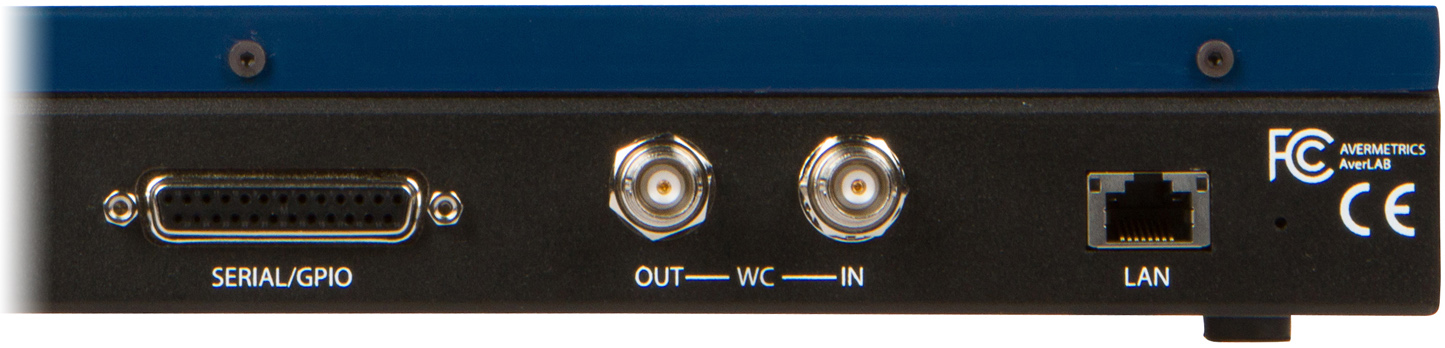
SERIAL/GPIO
Note that the features below are implemented in hardware, but are not exposed in the current version of AverLAB. They are documented here to show upcoming capabilities.
Up to 8 bits of parallel I/O, SPI with one Chip Select line, and I2C (Master Mode) are available via the SERIAL/GPIO port. In addition, I2S is available, and the I2S clocks may be set to be either input (from the external device) or output (from AverLAB). I2S is independent of, and may operate at the same time as the other GPIO signals.
All inputs and outputs are 3.3V CMOS logic levels, and are internally pulled high with 47K pullup resistors.
The GPIO port connections are via a female DB-25 connector with the following pinout:
| Pin | Signal | Pin | Signal |
| 1 | GPIO0/SPI_CS | 14 | Ground |
| 2 | GPIO1 | 15 | Ground |
| 3 | GPIO2 | 16 | Ground |
| 4 | GPIO3 | 17 | Ground |
| 5 | GPIO4/I2C_SCL/SPI_SCK | 18 | Ground |
| 6 | GPIO5/I2C_SDA/SPI_MOSI | 19 | Ground |
| 7 | GPIO6/SPI_MISO | 20 | Ground |
| 8 | GPIO7 | 21 | Ground |
| 9 | I2S_LRCK | 22 | Ground |
| 10 | I2S_MCLK | 23 | Ground |
| 11 | I2S_BCLK | 24 | Ground |
| 12 | I2S_SDATA_OUT | 25 | Ground |
| 13 | I2S_SDATA_IN |
Parallel I/O
Up to 8 bits of input and/or output may be configured for parallel operation. These signals are configurable for input or output in three banks: one set of 4 bits and two sets of 2 bits each, as shown.
| Bank | GPIO Bit |
| 0 | 0 |
| 0 | 1 |
| 0 | 2 |
| 0 | 3 |
| 1 | 4 |
| 1 | 5 |
| 2 | 6 |
| 2 | 7 |
Thus, the 4 bits in bank 0, as a group, may be set as either input or output, while the bits in bank 1 (and bank 2) may be independently set as input or output.
SPI I/O
When the GPIO port is configured for SPI, the lowest 4 bits are always outputs, with bit 0 configured as the chip select (Strobe) output and the other three bits driven high. Bits 4 and 5 are outputs, configured as SCK and MOSI, respectively, while bit 6 is an input, configured at MISO. The unused parallel outputs are not available when in SPI mode. However, the I2S lines are fully functional in this configuration.
Data rates of 100Kb, 400Kb, 1Mb, and 2Mb are supported, with SPI modes 0, 1, 2, 3 available for all clock configurations. Chip Select is always true low.
I2C I/O
When the GPIO port is configured for I2C, the lowest 4 I/O bits are available as parallel inputs or outputs. Bits 4, the SCL signal, is an output, while bit 5, the SDA signal is either an input or an output, as required by the I2C protocol. This feature is intended for configuring or controlling external devices such as Codecs and shift registers.
Data rates of 100Kb and 400Kb are supported, and the I2C port is always a master, and thus initiates all transactions.
Word Clock In/Out
Word Clock, also called Frame Sync or External Sync, can be used to synchronize the digital audio analyzer and generator to an external device. To synchronize AverLAB to an external clock source, connect the clock signal to the Word Clock In BNC. This input expects clock signals greater than 350 mVp-p (and up to 5Vp-p) at frequencies of 44.1 kHz, 48 kHz, 88.2 kHz, 96 kHz, 176.4 kHz, or 196 kHz, ±6%. The input impedance is nominally 75 ohms. Once connected, set the Sync Source in the AverLAB software to External so that this signal is used by the AverLAB hardware for sync.
The Word Clock output is a nominal 5V square wave at the current digital audio sample rate. This port is designed to drive a 75 ohm load.
Note that these Word Clock signals are not the same as those used by the ADC and DAC in the analog portion of AverLAB. Word Clock only applies to the digital audio section.
Ethernet LAN Port
This is the 100Base-T Ethernet connection to your host computer or local area network switch or router using the supplied Ethernet cable, or any good quality Cat5e or better cable. The cable may be “normal” or “crossover” type; AverLAB will automatically adjust for either kind of cable.
Be careful when connecting your network to AverLAB, as the Remote Port and AverLink A port are similar connectors to the LAN port. Connecting to the wrong port will do no harm, but of course AverLAB will not operate properly if the wrong ports are used. Note that an AverLink or Remote cable will not work as a replacement for the Ethernet cable. Use a proper Ethernet cable for the LAN connection.
Parameter Reset Button
Just below the FCC logo is a small hole. To reset all settings, such as the device name and network configuration, turn off the unit and insert a paperclip in the hole. Depress the button inside AverLAB, and while holding it depressed turn AverLAB on. The FN1 button on the front panel will flash rapidly to indicate it has reset the parameters. Release the button and turn AverLAB off and back on again. The unit’s configuration will be reset to:
- Device Name: AverLAB
- IP Address: DHCP
Theory of Operation
The AverLAB system consists of data collection and processing hardware, firmware that performs many measurement tasks autonomously, onboard DSP for some measurement tasks, and software and host-based DSP for measurement post-processing and display. This section discusses the theory of operation of the hardware part of the system, including the analog sections of AverLAB.
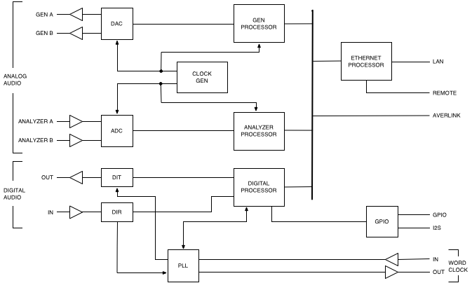
The AverLAB hardware is made up of four measurement subsystems, interconnected via a high-speed communication bus called AverLink. A signal-conditioned connection to the bus is exposed for expansion via the AverLink A port. The four subsystems correspond to individual independent modules, similar to the hardware modules used in AverLine. In fact, each of these modules is addressable via Ethernet exactly as if they were physically separate. AverLAB contains all of these functions on a single board, allowing some common functions to be shared across these subsystems, saving cost, power, and space.
The four logical modules are: Analog Generator, Analog Analyzer, Digital Generator and Analyzer, and Ethernet Interface. Each module in the system is identified by a model number and an ID. The model number tells an application such as the AverLAB host software what capabilities are available. The ID allows each module to be directly addressed and provides a mechanism to indicate the source of data for a measurement result. ID’s are 8-bit values, so 256 are available. However, one is always used for internal communication (ID 255), and each AverLink port can handle up to 128 ID’s. An AverLink A port addresses ID’s greater than 128, while an AverLink B port (seen on AverLine systems) address ID’s less then 128. Since four ID’s are used by the modules in AverLAB, this leaves 123 available ID’s, ranging from 132 to 254.
Ethernet Host Adapter Module
This module, referred internally as the 3003 Ethernet Host Adapter, acts as the communication hub of the system. It also manages the test process and data collection for all of the other modules in the system. In the case of an AverLAB that has been expanded using external AverLine racks and modules, the 3003 also manages all of those modules as well. The ID of this module is always 128.
This module accepts commands via a standard Telnet connection and distributes instructions to any modules that will be affected by those command. Those modules execute the command, whether a setting change or a test command, and the 3003 collects responses from the affected modules. Any responses are then forwarded to the host computer. All communications with the host are done using XML, which is a human-readable format consisting of tags, attributes, and data. XML is a widely used format that is related to the HTML used in web pages, and provides a very flexible communication protocol for AverLAB.
Analog Generator Module
The Analog Generator module; internally identified as model 4122, consists of a high-performance DAC, analog circuitry to condition the DAC output to produce the appropriate levels for output, and a multicore processor/DSP for control and processing. It is addressed as ID 129 by the software. This module shares a clock generator circuit with the Analog Analyzer module. However, the clock rates for these two modules are individually configured based on the requirements of a given measurement, and may not be running at the same sample rate.
For the generator, the sample rate is determined by the highest frequency that either output is currently set to generate. Up to 22 kHz, a sample rate of 48 kHz is used, while generator frequencies above 44 kHz use a sample rate of 192 kHz. For generator frequencies between 22 kHz and 44 kHz the sample rate is set to 96 kHz. Currently, two independent frequencies may be generated simultaneously, and they may be routed to either or both outputs.
Analog Analyzer Module
This module, internally referred to as model 4022, consists of analog circuitry to condition the input signals for processing by a high-performance ADC, and a multicore processor/DSP for control and processing. It is addressed as ID 130 by the software. Depending on the test requirements, measurements may be entirely processed by the onboard DSP, partially processed onboard and partially on the host computer, or sample data is transferred to the host for more complex processing.
Digital Audio Generator/Analyzer Module
This module, model 4103, provides digital interfaces for S/PDIF, optical (Toslink), AES/EBU, and ADAT, and generates and analyzes digital audio at all standard sample rates. A hybrid digital/analog phase locked loop (PLL) circuit provides clock extraction and regeneration for all formats, so that the data may be synchronized properly in all formats. Currently, cross-format generator and analyzer measurements are not supported by the AverLAB hardware. However, complex system tests that output on one format and receive on another may be done using an external AverLine rack and suitable digital audio module. In that configuration, any number of channels using any available format may be mixed in a given measurement.
This module also controls the GPIO subsystem. Configurable bi-directional buffers and a separate I2S receiver and transmitter make this I/O port very flexible. Automatic event triggers based on state are included in the implementation. However, currently this functionality is not exposed in the software, but will be available in a near-term update.
Analog Generator Output
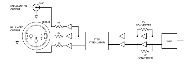
For each channel, the analog circuitry of the generator output consists of a pair of current-to-voltage (I/V) converters, buffers, and a step attenuator, as shown. The DAC has a balanced current output, and the I/V converters change that into voltage at the proper level. This level is then reduced by the attenuator as required to get the final output. The fully balanced attenuator has nine 6 dB steps, including 0 dB attenuation. This scheme allow the system to hold the DAC output within a 6 dB window, which provides the best possible noise and distortion performance over a wide output range. For the balanced output, the differential output impedance is nominally 40 ohms, while the unbalanced output has a 20 ohm impedance.
Analog Analyzer Input
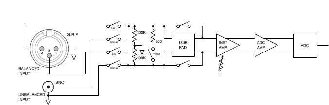
The analog input circuitry consists of a relay input selector, switchable 600 ohm termination, switchable 18 dB pad, variable gain instrumentation amp, and an ADC driver amp. With the termination and 18 dB pad switched off, the input signal is applied directly to the instrumentation amp. For the unbalanced input, the same input circuit is used, and the hot (+) input is applied normally to the input stage. However, in this case the cold (-) is connected to the BNC’s shell, which is insulated from the AverLAB case. Note that the BNC is connected to signal ground inside the unit, so care is required to prevent inadvertent short circuits with the device under test, as with any unbalanced input or output.
The fully balanced instrumentation amp gain is adjustable in 6 dB steps using high-reliability relays. There are 9 steps of gain available, including a gain of 1. The output of the instrumentation amp is applied to the ADC driver amp, which reduces the signal level to match the ADC input range. This stage also provides the appropriate offset and signal conditioning required by the ADC.
When idle, the system has the 600 ohm termination off and the 18 dB pad engaged. This protects the input circuitry while still allowing the system to monitor input levels while idle. Normally, the 18 dB pad is switched off when making a measurement. However, since the inputs are fully DC coupled it is possible to measure DC and DC + AC signals. In that case, the 18 dB pad is kept on, dividing the input voltage by a factor of 8. Because the inputs also have protections circuits (not shown) that limit the maximum voltage that the instrumentation amp will see, the maximum voltage, DC or AC that can be measured is approximately 70V. Voltages up to 50V can be measured with high accuracy using this circuit. The input impedance with or without the 18 dB pad engaged is approximately 200K ohms differential. While the ability to make DC measurements is not currently enabled in the software, it will be available in a future update.